- 您现在的位置:买卖IC网 > Sheet目录340 > MAX17105ETG+T (Maxim Integrated)IC LED DRVR WHITE BCKLGT 24-TQFN
8-String WLED Driver with Integrated Step-Up
Regulator and SMBus/PWM Dimming Capability
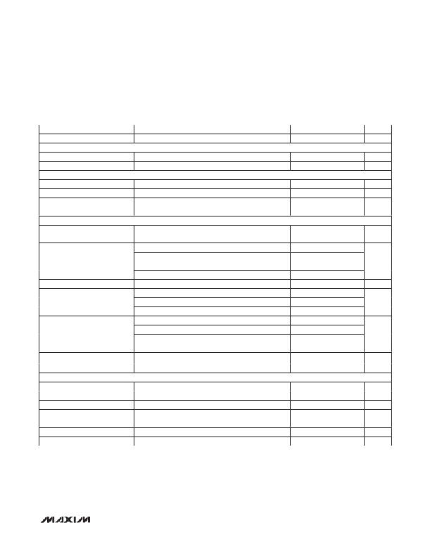
ELECTRICAL CHARACTERISTICS (continued)
(Circuit of Figure 1. V IN = 12V, C COMP = 33nF, R COMP = 1k I , R ISET = 50k I , R OSC = 100k I , R DFSET = 250k I , PWMI = SGND,
C PWMO = 1μF, T A = 0 N C to +85 N C , unless otherwise noted. Typical values are at T A = +25 N C.)
PARAMETER
LX Current Limit
CONDITIONS
Duty cycle = 75% (Note 1)
MIN
2.4
TYP
2.9
MAX
3.4
UNITS
A
CONTROL INPUT
Logic-Input High Level
Logic-Input Low Level
SDA, SCL, PWMI, EN
SDA, SCL, PWMI, EN
2.1
0.8
V
V
INPUT LEAKAGE
PWMI Leakage Current
Logic Input Bias Current
OVP Leakage Current
SDA Output-Low Sink Current
T A = +25 N C
T A = +25 N C, EN, SDA, SCL
TA = +25 N C
V SDA = 0.4V
-0.1
-1
-0.1
4
+0.1
+1
+0.1
F A
F A
F A
mA
LED CURRENT
Full-Scale FB_ Output Current-
Adjustable Range (Note 4)
PWM-only dimming mode
SMBus-enabled dimming modes
R ISET = 33.3k I
15
15
29.1
30.0
30
25
30.9
mA
Full-Scale FB_ Output Current
ISET Output Voltage
R ISET = 50.0k I
R ISET = 66.6k I
V ISET < 0.4V
19.4
14.45
0.2
1.1
20.0
15.0
0.3
1.2
20.6
15.55
0.4
1.3
mA
V
Current Regulation Between
Strings
Minimum FB_ Regulation
Voltage
FB_ On-Resistance
FB_ Leakage Current
FB_ On-Time
I FB_ = 30mA
I FB_ = 20mA
I FB_ = 15mA
I FB_ = 30mA
I FB_ = 20mA
I FB_ = 15mA
V FB_ = 50mV
V FB_ = 40V, T A = +25 N C
-2.0
-2.0
-2.0
400
480
450
15
0.1
+2.0
+2.0
+2.0
770
26
5
%
mV
I
F A
ns
FAULT PROTECTION
OVP Threshold Voltage
Rising edge, hysteresis = 60mV
1.15
1.25
1.35
V
OVP Shutdown Voltage
OVP Global Fail
Rising edge
48
1.35
120
V
mV
FB_ UVLO Threshold
FB_ Overvoltage Threshold
FB open
140
7.4
220
8
300
8.6
mV
V
FB_ Check LED Source Current
FB_ Check LED Time
0.4
1
mA
ms
________________________________________________________________________________________
3
发布紧急采购,3分钟左右您将得到回复。
相关PDF资料
MAX17127ETP+
IC WLED DVR SIX STRING 20TQFN
MAX17149ETE+
IC LED DRVR 6CH STEP UP 16QFNEP
MAX17410EVKIT+
KIT EVAL FOR MAX17410 CTLR
MAX17605AUA+
IC MOSFET DRVR 4A DUAL 8UMAX
MAX1848ETA+T
IC LED DRIVR WHITE BCKLGT 8-TDFN
MAX1912EUB+
IC LED DRVR WHITE BCKLGT 10-MSOP
MAX1916EZT+T
IC LED DVR WHITE BCKLGT 6TSOT
MAX1986ETE+T
IC LED DRVR WHITE BCKLGT 16-TQFN
相关代理商/技术参数
MAX17105EVKIT+
功能描述:电源管理IC开发工具 MAX17105 Eval Kit RoHS:否 制造商:Maxim Integrated 产品:Evaluation Kits 类型:Battery Management 工具用于评估:MAX17710GB 输入电压: 输出电压:1.8 V
MAX17106ETN+
功能描述:PMIC 解决方案 PMIC for LCD RoHS:否 制造商:Texas Instruments 安装风格:SMD/SMT 封装 / 箱体:QFN-24 封装:Reel
MAX17106ETN+T
功能描述:其他电源管理 Integrated Circuits (ICs) Power Management - Specialized - IC REG STEP UP/HV STEPUP 56-TQFN RoHS:否 制造商:Texas Instruments 输出电压范围: 输出电流:4 mA 输入电压范围:3 V to 3.6 V 输入电流: 功率耗散: 工作温度范围:- 40 C to + 110 C 安装风格:SMD/SMT 封装 / 箱体:VQFN-48 封装:Reel
MAX17106EVKIT+
制造商:Maxim Integrated Products 功能描述:STEP-UP REGULATOR HIGH-VOLTAGE STEP-UP WITH TEMPERATURE COMP - Boxed Product (Development Kits)
MAX17107ETI+
制造商:Maxim Integrated Products 功能描述:- Rail/Tube
MAX17108ETI+
功能描述:LCD Gamma缓冲器 10Ch Scan Driver & VCOM Amp RoHS:否 制造商:Maxim Integrated 输入补偿电压: 转换速度: 电源电压-最大:20 V 电源电压-最小:9 V 电源电流: 最大功率耗散: 最大工作温度:+ 85 C 安装风格:SMD/SMT 封装 / 箱体:TQFN-38 封装:Tube
MAX17108ETI+T
功能描述:LCD 驱动器 10Ch High-Volt & VCOM Amp RoHS:否 制造商:Maxim Integrated 数位数量:4.5 片段数量:30 最大时钟频率:19 KHz 工作电源电压:3 V to 3.6 V 最大工作温度:+ 85 C 最小工作温度:- 20 C 封装 / 箱体:PDIP-40 封装:Tube
MAX17108EVKIT+
功能描述:电源管理IC开发工具 MAX17108 Eval Kit RoHS:否 制造商:Maxim Integrated 产品:Evaluation Kits 类型:Battery Management 工具用于评估:MAX17710GB 输入电压: 输出电压:1.8 V
